
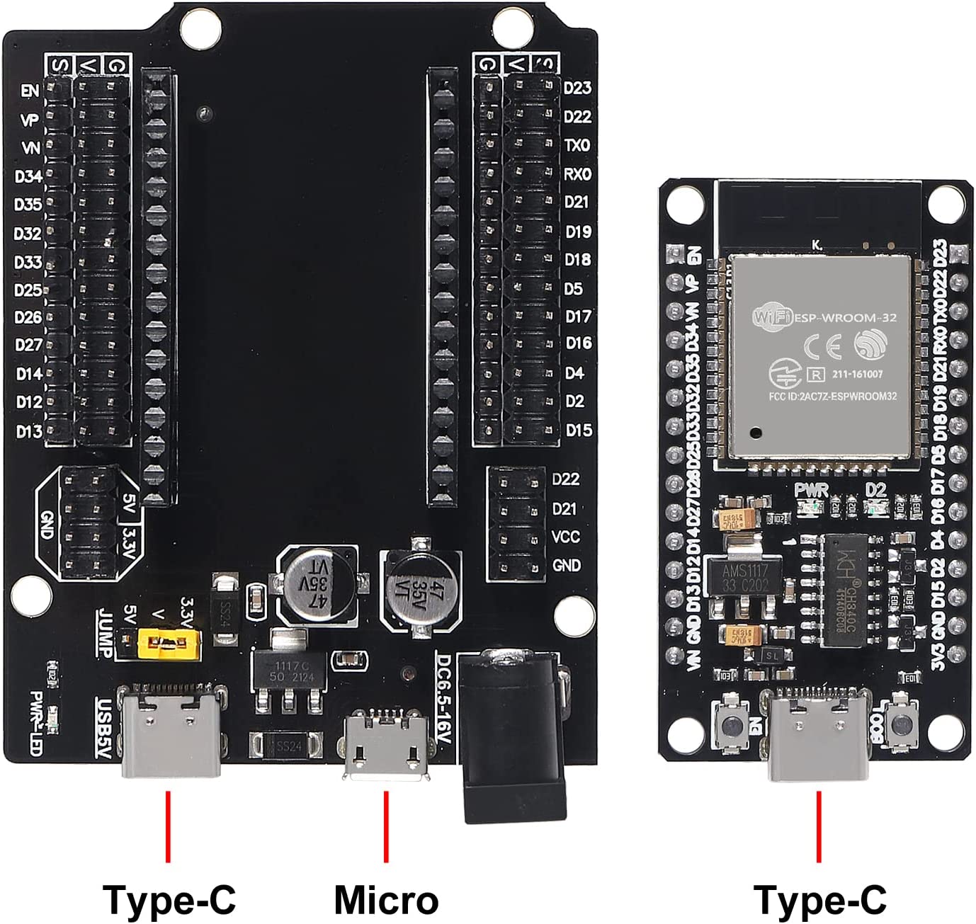
ESP32 Dev Board
Tutorials
Article Here
ESP32-WROOM-32 Download mode
EN - reset
Boot IO0
Hold Boot button, Press & release Reset button
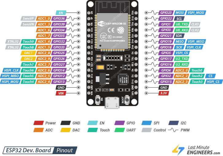
Analog to Digital Converter (ADC)
- ADC1_CH0 (GPIO 36) *
- ADC1_CH1 (GPIO 37)
- ADC1_CH2 (GPIO 38)
- ADC1_CH3 (GPIO 39) *
- ADC1_CH4 (GPIO 32) *
- ADC1_CH5 (GPIO 33) *
- ADC1_CH6 (GPIO 34) *
- ADC1_CH7 (GPIO 35) *
- ADC2_CH0 (GPIO 4)
- ADC2_CH1 (GPIO 0)
- ADC2_CH2 (GPIO 2)
- ADC2_CH3 (GPIO 15)
- ADC2_CH4 (GPIO 13)
- ADC2_CH5 (GPIO 12)
- ADC2_CH6 (GPIO 14)
- ADC2_CH7 (GPIO 27)
- ADC2_CH8 (GPIO 25)
- ADC2_CH9 (GPIO 26)
Analog Inputs (ADC)
Reading an analog value with the ESP32 means you can measure varying voltage levels between 0 V and 3.3 V.
The voltage measured is then assigned to a value between 0 and 4095, in which 0 V corresponds to 0, and 3.3 V corresponds to 4095. Any voltage between 0 V and 3.3 V will be given the corresponding value in between.
Even though ESP32 has 18 channels ADC, all the ADC pins are not available for the user. Of the 8 ADC1 channels, only 6 are available (ACD1_CH0 and ACD1_CH3 to ACD1_CH7) while ADC1_CH1 and ADC1_CH2 are not available (even the pins are not exposed in the ESP32 Development Board).
analogRead() Function
Reading an analog input with the ESP32 using the Arduino IDE is as simple as using the analogRead() function. It accepts as argument, the GPIO you want to read:
analogRead(GPIO);
These analog input pins have 12-bit resolution. This means that when you read an analog input, its range may vary from 0 to 4095.
ESP32 I2C Communication
Connecting an I2C device to an ESP32 is normally as simple as connecting GND to GND, SDA to SDA, SCL to SCL and a positive power supply to a peripheral, usually 3.3V (but it depends on the module you’re using).
| I2C Device | ESP32 |
| SDA | SDA (default is GPIO 21) |
| SCL | SCL (default is GPIO 22) |
| GND | GND |
| VCC | usually 3.3V or 5V |
SPI
For SPI communication you need four lines:
- MISO: Master In Slave Out
- MOSI: Master Out Slave In
- SCK: Serial Clock
- CS /SS: Chip Select (used to select the device when multiple peripherals are used on the same SPI bus)
Many ESP32 boards come with default SPI pins pre-assigned. The pin mapping for most boards is as follows:
| SPI | MOSI | MISO | SCLK | CS |
| VSPI | GPIO 23 | GPIO 19 | GPIO 18 | GPIO 5 |
| HSPI | GPIO 13 | GPIO 12 | GPIO 14 | GPIO 15 |
Oled
see here
|
OLED Display |
ESP32 (VSPI) | ESP32 (HSPI) | |
| GND |
GND |
GND |
|
|
VCC |
3.3V | 3.3V | |
| D0 (SCK) |
GPIO 18 (D18) |
GPIO 14 (D14) |
|
|
D1 (MOSI) |
GPIO 23 (D23) | GPIO 13 (D13) | |
| RES (any gen pin) |
GPIO 17 (TX2) (D17) |
GPIO 17 (TX2) (D17) |
|
|
DC (any gen pin) |
GPIO 16 (RX2) (D16) | GPIO 16 (RX2) (D16) | |
| CS |
GPIO 5 (D5) |
GPIO 15 (D15) |
|
ESP32 with Multiple SPI Devices
As we’ve seen previously, you can use two different SPI buses on the ESP32 and each bus can connect up to three different peripherals. This means that we can connect up to six SPI devices to the ESP32. If you need to use more, you can use an SPI multiplexer.